3D Printed Jigs, Fixtures & Tooling: Accelerating Manufacturing with Advanced Filaments
Engineers are replacing conventional machined or molded tooling with 3D printed jigs, fixtures, and tooling made from engineering-grade and ultra-polymers. Using materials like Nylon, Polycarbonate (PC), Carbon-Fiber blends, PEEK, and Ultem (PEI) delivers lighter, customized, and cost-effective tools that speed production and improve quality control.
Keywords: 3D printed jigs, 3D printed fixtures, 3D printed tooling, nylon tooling, carbon fiber filament tooling, PEEK tooling, Ultem tooling, additive manufacturing jigs.
Why Use 3D Printed Tooling?
Traditional tooling manufacturing (machining, injection mold, cast) can be slow and expensive—especially for low-volume or highly customized tools. Additive manufacturing (AM) offers distinct advantages:
- Speed: Produce functional jigs and fixtures in hours or days, not weeks.
- Cost: Lowers upfront tooling costs and eliminates expensive fixtures for one-off or short runs.
- Customization: Tailor-fit tools for complex parts, ergonomic operator aids, or lineage-specific assembly.
- Weight & Handling: Lightweight tools reduce operator fatigue and speed cycle times.
- Iterative Design: Rapidly refine tooling geometry based on shop-floor feedback.
Materials for Jigs, Fixtures & Tooling
Select a filament based on mechanical load, temperature exposure, chemical contact, and lifecycle demands. Common, reliable options include:
Nylon (PA) & Reinforced Nylons
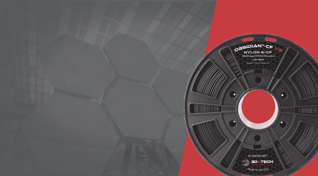
Nylon is tough, wear-resistant, and slightly flexible—ideal for clamps, sliding fixtures, and wear-prone components. Reinforced variants (carbon- or glass-fiber filled Nylons) increase stiffness and dimensional stability for precision tooling.
Polycarbonate (PC)
PC provides high impact strength and excellent heat resistance. Use PC for tooling that sees elevated temperatures, heavier mechanical loads, or requires precise fit. See our full Polycarbonate filament guide.
Carbon-Fiber Reinforced Blends
Carbon-fiber blends (PC-CF, Nylon-CF) boost stiffness and reduce part deflection—useful for long-span fixtures or tooling requiring high stiffness-to-weight ratios.
ABS & FR-ABS
ABS is easy to print and cost effective for low-stress fixtures. FR-ABS variants add flame resistance for environments with safety requirements.
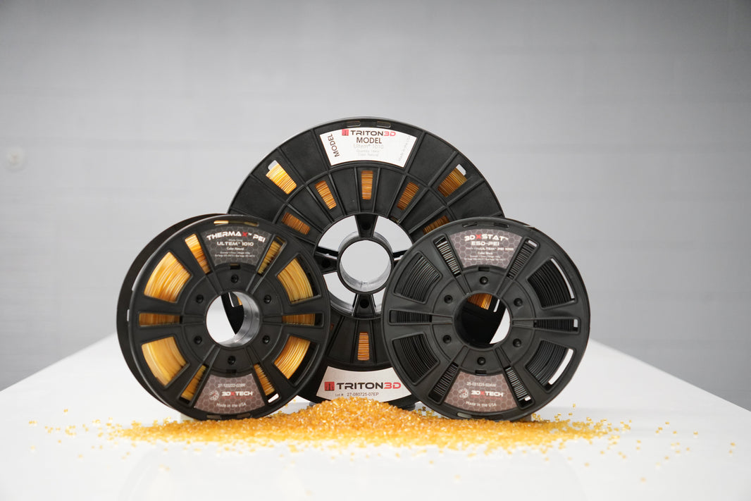
Ultra-Polymers (PEEK, PEKK, Ultem/PEI)
When tooling must withstand extreme heat, chemicals, sterilization, or long-term mechanical stress, ultra-polymers are the choice. PEEK and PEKK offer exceptionally high continuous-use temperatures and chemical resistance; Ultem (PEI) adds inherent flame retardancy and dimensional stability. See our ultra-polymer comparison for details.
Common Applications
- Assembly Jigs: Positioning and alignment tools for complex assemblies.
- Inspection Fixtures: Gauges and holders for quality control and automated vision systems.
- End-of-Arm Tooling (EOAT): Lightweight grippers and tooling for robotic arms.
- Workholding Fixtures: Clamps, nests, and soft-jaws for machining or manual assembly.
- Short-Run Production Tooling: Soft molds, inserts, and guides for limited production batches.
- Operator Aids: Ergonomic handles, gauges, and templates to reduce human error.
Design & Process Best Practices
Design for Additive Manufacturing (DfAM)
- Orient parts for strength in load directions and minimize supports that create weak interfaces.
- Use fillets, ribs, and honeycomb/lattice infill to combine stiffness with reduced mass.
- Design in replaceable wear surfaces or sacrificial inserts to extend tool life.
Material & Printer Setup
- Match material to environment: e.g., Nylon for wear, PC for heat, PEEK/Ultem for extreme conditions.
- Use appropriate build surface, heated bed, and enclosed chamber for high-temp materials.
- Dry hygroscopic filaments (e.g., Nylon, PEEK) before printing to avoid delamination and poor surface finish.
Post-Processing & Finishing
- Anneal or stress-relieve ultra-polymers when dimensional stability is critical.
- Machine mating surfaces, add threaded metal inserts, or apply coatings for wear resistance.
Quality, Testing & Lifecycle
Treat printed tooling as qualified production equipment: document material lot numbers, print profiles, and testing data. Recommended checks include:
- Tensile and flexural test coupons for new material batches.
- Dimensional inspection of mating features after post-processing.
- Wear tests for sliding fixtures and clamp points.
- Service-life tracking and predefined replacement intervals for high-cycle tools.
Example Workflows
Rapid Iteration: From Concept to Shop Floor
- Print lightweight prototype in PLA/ABS to validate form and ergonomics.
- Refine geometry and print final fixture in Nylon or PC for functional trials.
- Install metal inserts or harden contact surfaces; run on-line for production validation.
Production Transition: Tooling to End-Use
- Validate tooling performance; collect cycle and wear data.
- Migrate to higher-performance material (e.g., PEEK or Ultem) if operating temperatures or chemical exposure demand it.
- Document parameters and maintain digital inventory for fast reprints and spares.
Conclusion & Next Steps
3D printed jigs, fixtures, and tooling provide a fast, flexible, and cost-effective route to modern manufacturing. By selecting the right filament, following DfAM principles, and enforcing quality controls, teams can reduce lead times, cut costs, and improve assembly quality. For further reading and material deep dives, check our posts on Nylon, Polycarbonate, and PEEK / PEKK / Ultem.


